

Repair of Vinnie Zummo's Vintage Maestro FZ-1 Fuzz
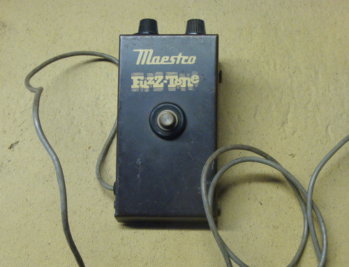
NYC Guitarist / Producer Vinnie Zummo asked me the repair his vingtage Maestro FZ-1 Fuzz. The pedal was a dead soldier.
There are quite a few schematics posted on the internet, but I decided since I had the real McCoy right in front of me, the first thing to do was draw out a schematic. Click on the image to see a larger version.

You might note from the schematic above this is a positive ground pedal, therefore not such a great match for the modern day pedal board. Three transistors are employed, the first of which (Q1) is configured as an emitter follower where the base of the transistor serves as the input, the emitter is the output, and the collector is common to both. It is used to set a high input impedance. Q2 & Q3 are configured as common-emitter amplifiers, where the base serves as the input, the collector is the output, and the emitter is common to both. You will note there are 2 pots: a 50K gain pot, and a 500K volume pot. The volume pot has a 56K resistor in parallel with it, effectively bringing the pot value down to approximately 50K. One point of interest is the selection of a 3300 pf capacitor on the output. This forms a high pass filter when coupled with the volume pot, with a cutoff frequency of somewhere in the ballpark of 964 hz, so as designed this pedal really emphasizes high end. The pedal has both a foot switch and a switch on the volume pot. The 2 poles of the foot switch are located in the on far left and far right of the drawing. One other point to mention is this circuit absolutely requires very leaky transistors.
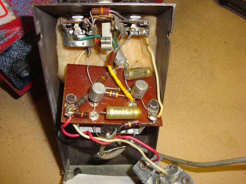
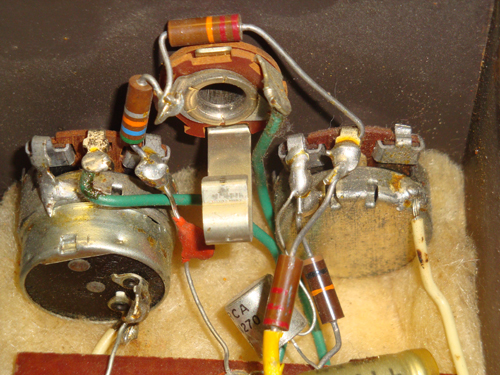
The next 5 images are for those interested in seeing the guts of an original FZ-1
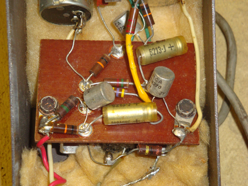
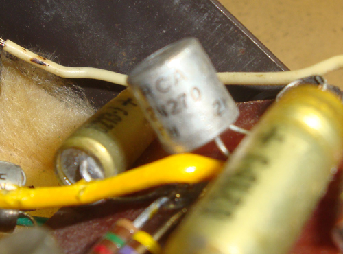
Close up of RCA 2N270 germanium PNP transistor
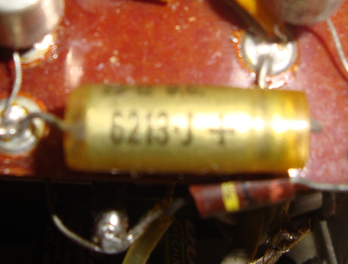
Closeup of one of the Sprague capacitors - notice the date code 6213 indicating the 13th week of 1962
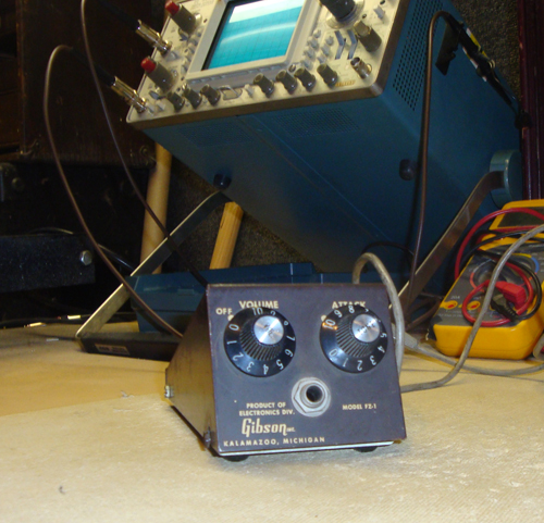
TROUBLESHOOTING
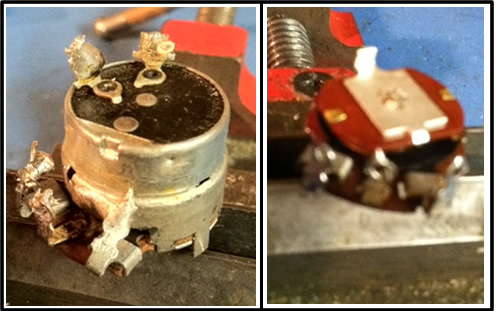
Thef first thing I determined after some puttering around with the oscilloscope, was that the switch attached to the volume pot was bad. In the spriit of trying to preserve all the original parts, I then removed the switch/pot from the pedal and took it apart to clean it out in an attempt to preserve/restore it. The good news is both the switch and pot are now working fine. The bad news was that 56K resistor crumbled into pieces in the process. I therefore replaced that resistor with a new one.
'
It is s cool sounding pedal, and one that would pretty easy to clone provided you get some leaky germanium transistors. The circuit is designed to run off a 3V supply, so a convenient approach would be to use a 9V battery with a voltage regulator such as the LM317.